02
10 2025
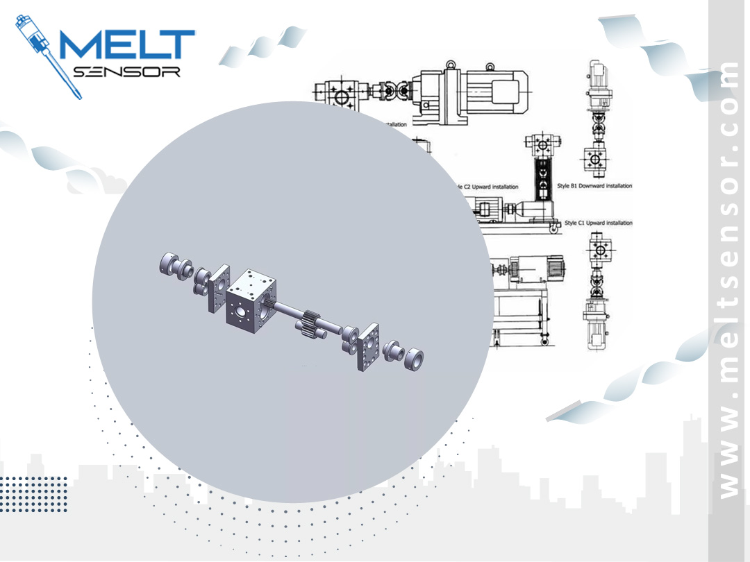
Gear Pump Pressure Architectures
Melt – Gear Pump Pressure Architectures (Best Practices)
1) Pump Speed Control via Pump Inlet Pressure (Recommended)
Measurement: Monitoring pressures with melt pressure sensors before the gear pump (the most common method).
Manipulated Variable: Pump Speed
Advantage: "Strains" extruder fluctuations, coupled with constant flow to the die/metering unit.
2) Feedback via Extruder Speed
With a fixed pump speed, the extruder speed varies according to pressure sensor values.
Stable operation across a wide range of raw materials, but slower response than option 1.
3) Cascade (Inner-Outer Loop)
Inner loop: Pump speed control
Outer loop: Pressure control (continuous monitoring via melt pressure sensors)
Fast, stable, and noise-resistant; preferred in advanced production lines.
Practical Starting Values for PID Settings
The cap and material are different; the starting days are in the following ranges:
P (Gain): 0.8–2.5 (note the %/bar scaling on the analog output)
I (Derivative Time, integral): 3–8 s (zeroes that do not cut off the pressure drift)
D (Derivative): 0–0.5 s (usually kept low, note the noise amplification)
Filter (PV filter): 0.1–0.5 s (smoothes noise from melt pressure sensor signals)
Output Limit: Minimum–Maximum pump speed limit (e.g., 10%–90%)
Ramp/Soft Start: 10–30 s to maintain unheated material during startup
Tip: First use P for fast response, then I for permanent smoothing; only useful for real acceleration/sudden load changes.
Alarm and Safety Scenarios
HI Pressure (e.g., set point + 30 bar): Pump stop + Extruder slowdown
Sensor Failure / Cable Break: In the event of a pressure sensor failure, the pump will switch to a safe speed (e.g., 10%) or an emergency stop will be applied.
Overtemperature: Even if the pressure control circuit remains, the heaters and extruder speed will be switched to a safe mode.
Backpressure (die blockage): Operator warning + speed reduction on HI alarm.